
1939 Analysis of Beam Ray Machine
This page contains a more detailed description and brief analysis of the operation of the Beam Ray machine.
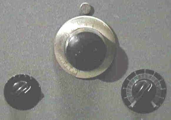
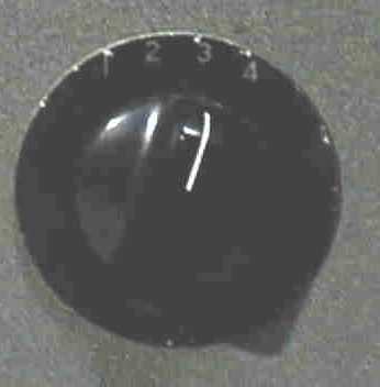
Operation
The machine has 3 external controls. The leftmost one is a 4 way rotary switch with positions labelled 1 through 4. These are the (modulation) frequency bands of the machine. The total range of the modulation settings is from approximately 20 Hz to 200 Khz in 4 decades as follows:
Band Setting |
Frequency Range |
|
|
|
|
|
|
|
|
|
|
|
|
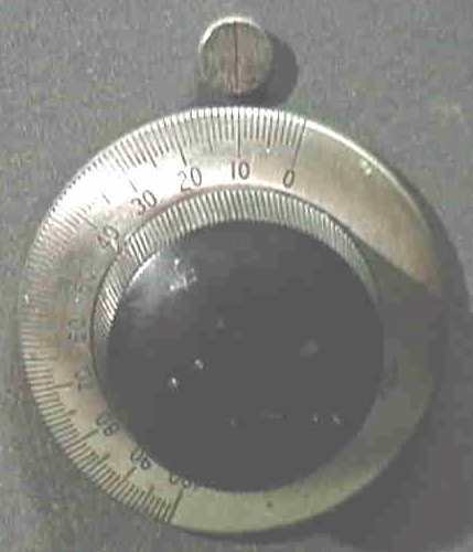
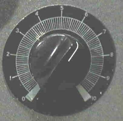
The centre control is the main modulation frequency dial. This is calibrated in one step units from 0-100. The dial superficially appears to be a vernier dial but isn't, although it is finely marked, of good quality and is geared down, so a single turn does not move it completely from end to end. A resolution of 1/2 a division is easily possible.
The actual frequency setting for any given dial setting is not linear. For example setting the frequency dial to 50 in band 3 does not guarantee you'll get 10 KHz. The variation of the actual frequency for any given dial setting follows an approximate 3rd degree polynomial curve.
Treatment Settings
The machine came with some old diary pages with a series of treatment settings scribbled on them. The year of the diary was not shown, just the months but February was shown. It was not a leap year and by matching the days of the week to the dates it had to be 1939. There were the "usual" Rife pathogens plus a few more ailments that I had never seen quoted on any other early Rife machine list. Unfortunately they were not all complete so it wasn't possible to derive the true frequencies for all of them. The anomalies included:
"V" with a setting of band 3, dial 39 - but I have no idea what this is.
"Radiation" with a strange setting of "2-17-3" which could mean band 2 or 3 dial setting 17.
Pain - "20", Iodine Poisoning - "92", Mercury Poisoning - "55", Tissue repair - "58", Scar Tissue - "13", Mucous Colitis - "38", Haemorrhoid - "88", Catarrh - "17", Inflammation - "40" and Irritation - "30".
The ones that could be clearly resolved are shown in the table on the right.
Pathogen |
Band |
Dial |
Frequency (Hz) |
BX |
4 |
10 |
21275 |
Sarcoma |
4 |
6.5 |
20080 |
Typhoid Virus |
3 |
94 |
18620 |
Tetanus |
2 |
78.5 |
1200 |
Treponema |
3 |
56 |
6600 |
GC+Typhoid? |
3 |
58.5 |
6900 |
Staphylococcus |
3 |
59 |
7270 |
Pneumonia |
3 |
61 |
7660 |
Streptothrix |
3 |
61.5 |
7870 |
Coli Rod |
3 |
62 |
8020 |
TB Rod |
3 |
63 |
8300 |
Streptococcus |
3 |
63.5 |
8450 |
TB Coli Virus |
3 |
88 |
16000 |
Coli Virus |
3 |
89.5 |
17220 |
Worms |
3 |
24 |
2400 |
Circuit Analysis
The most striking thing about the Beam Rays circuit at first glance is the oscillator section. The machine oscillator is clearly a first generation Hewlett Wein Bridge circuit. What makes this particularly notable is that Hewlett (Hewlett-Packard) only invented the circuit around the time the Beam Rays machine was built. Because it was so new and had not found its way into commercial designs it tends to imply that there might have been some connection between Hewlett and Beam Rays.
I have written a detailed account of the history entitled
The earlier Rife machines had used the Hartley oscillator circuit which was nowhere near as stable as the Hewlett Wein Bridge. So the use of this circuit was a big step forward for Beam Rays. The earlier machines had been plagued with apparent frequency instability which made consistent use very difficult. The Wein bridge circuit was an apparent solution, but in practice there was another factor that they apparently did not take into account.
The Beam Rays oscillator is remarkably stable - it drifts by only a few Hertz during normal operation and is superior to many modern analog generators. But it has one major drawback. Tuning is achieved by way of a variable capacitor. This capacitor is connected directly to the tuning dial. The tuning dial is a geared down dial that allows very precise turning of the capacitor shaft. However in practice it suffers from a slight degree of "backlash" - in other words, no matter how carefully you turn the dial, there is always some residual pressure on the rotary shaft - and left to itself for a while this residual pressure or tension causes the capacitor shaft to turn back by a small amount. This is enough to throw the tuning out by a couple of Hertz in the lowest range - and the problem multiplies by a factor of 10 for each higher range. So in the top range the backlash can throw the frequency setting off by approximately 2KHz. In addition, because the relationship between the dial setting and the actual frequency is non-linear, the problem is always worse toward the top of the scale (i.e. the dial is calibrated from 0 to 100 - the problem is much more pronounced near 100 than it is near 0). One of the ways in which this manifests most noticeably is that turning the dial down from a higher number results in a lower overall frequency than turning the dial up from a lower number to the same final setting.
The frequency setting is obviously critical and this may explain why some frequency stability related problems were encountered even with this extremely good oscillator.
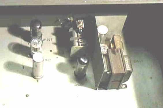
The presence of the Hewlett oscillator explains also the general build of the machine. When I examined the machine there were various minor anomalies. One of which was the size of the two chassis. They are both much bigger than they need to be. Also there are two separate chassis and the earlier Beam Rays machines had only one. Another thing is that there is a circuit on the oscillator stage which is not connected and not used. This was probably meant to be able to create square waves by sine overdrive and clipping. Finally the mounting holes on the chassis do not correspond with the mounting holes on the case - someone has drilled new holes in both chassis to remount them in the case. This could mean that the case the machine is in is not the original case it was shipped in. Alternatively it could mean that the chassis were previously mounted in a different way (maybe in a different case) prior to shipping.
Taking all these things together leads me to the conclusion that the machine I examined is probably an original prototype. This makes sense considering that the Hewlett oscillator was so new. Obviously, Phillip Hoyland or whoever built the machine decided to try making the oscillator stage separately from the output stage. The output stage is presumably the same as in earlier Beam Rays machines (it looks the same as a 1937 Beam Rays machine), but clearly they decided to build the oscillator on a separate chassis. The chassis were overlarge to allow for circuit expansion and modification. The unused circuit was probably tested at some point and found to be unnecessary. And it is likely that during development the different mountings were used on some sort of open frame to allow testing and measurement.
But this prototype machine was shipped and sold as a finished unit, why? The answer is probably quite obvious. The machine was produced during the great depression. Everything was expensive, Beam Rays was a small company and needed to keep down costs. The prototype was probably only needed during development. Once everything had been worked out satisfactorily, the prototype was no longer needed - and could be sold for a substantial profit, as it was effectively a working machine of a new design.
The 6SJ7 and 6K6(B) tubes on the combined schematic are the basic Hewlett Wein Bridge oscillator circuit. See "The Hewlett Connection" for a schematic of Hewlett's patented design. The third tube marked 6K6(A) is a simple cathode follower buffer stage, analogous to a modern transistor emitter follower circuit. This circuit has high input impedance, low output impedance and unity gain. It is designed to insulate the sensitive oscillator section from the following output stages. The 6SN7 tube is the unused circuit and as mentioned above was probably meant to be part of a fast clipper amplifier to produce square wave modulation.
The oscillator stage creates a pure sine wave from approx 20 Hz to 200KHz depending on range and dial setting. It also produces a variable amplitude output which can be adjusted from 0v right up to approx 50V peak to peak.
The output stage consists mainly of a single power triode. Although the machine had an 812A triode in it when I got it, I believe the correct original tube was an 809. The machine runs a lot more cleanly and stably with an 809 than an 812A. The stage is self-oscillating, it has a simple regenerative feedback arrangement from plate to grid via two capacitors and the tank coil. The degree of feedback can be adjusted by means of a large power resistor from the grid to ground. Note: the machine was not actually grounded, the negative end of the supplies connected to the chassis and all "grounds" were actually referenced to the chassis. I found in practice that the chassis did tend to accumulate quite a nasty residual charge after the machine had been operating and so I grounded it which did not seem to affect the operation of the machine. The output stage is actually a Hartley oscillator, although not obviously so, because the output capacitor in series with the plasma tube capacitance represents the "tuning" capacitance of the circuit. The large power resistor in series with the tube affects the oscillator loading, the output field impedance and also the Q of the resonant circuit. Because the plasma tube is an active circuit element, capacitive coupling from any body in the vicinity of the plasma tube actually causes changes in the oscillator frequency. The "resting" frequency of the output oscillator is around 3.3 MHz using the 812A and an Argon (Nazarov) phanotron tube. When the tube was was changed to an 809 and a 15mm Helium Cheb phanotron was used, the "resting" frequency changed to 4.68 Mhz and the wave became much more sinusoidal .
The output from the modulation oscillator stage is capacitively coupled to the output triode grid via an inductor. The latter is designed to prevent the carrier oscillations from feeding back into the modulation oscillator stage.
The DC HT power for the output triode is derived from a 1235 VAC plate transformer by two 866 mercury vapour rectifiers. The DC output is smoothed via a large choke and a filter capacitor to ground. There is also an RFC choke in the line to the plate. The net voltage at the plate of the triode is only around 550V DC which is consistent with a choke smoothed circuit. However much more interesting is the other end of the tube - the filaments (which double as cathodes) are connected to a direct AC filament heater transformer which means that there is an additional modulation at the 60Hz mains frequency (cathode modulation).
In practice during operation, the machine creates the carrier waveform (which is not very clean and contains a lot of harmonics - it has a superficial similarity to a sawtooth wave). UPDATE: the carrier waveform is smoother with the 809, but still contains some strong harmonics. The carrier is then amplitude modulated by the sine wave produced by the modulation oscillator. However, in addition, the AC cathode connection causes a further modulation at 60Hz. In effect the modulated wave is chopped into chunks or bursts that are one period of a 60 Hz cycle apart. And the envelope of the wave is effectively the first quarter cycle of a 60Hz cosine wave. In some respects this is like a very crude approximation to a damped wave. I believe that the latter is not a design flaw but rather a feature.
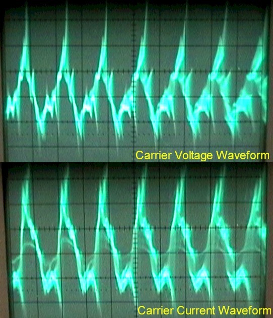
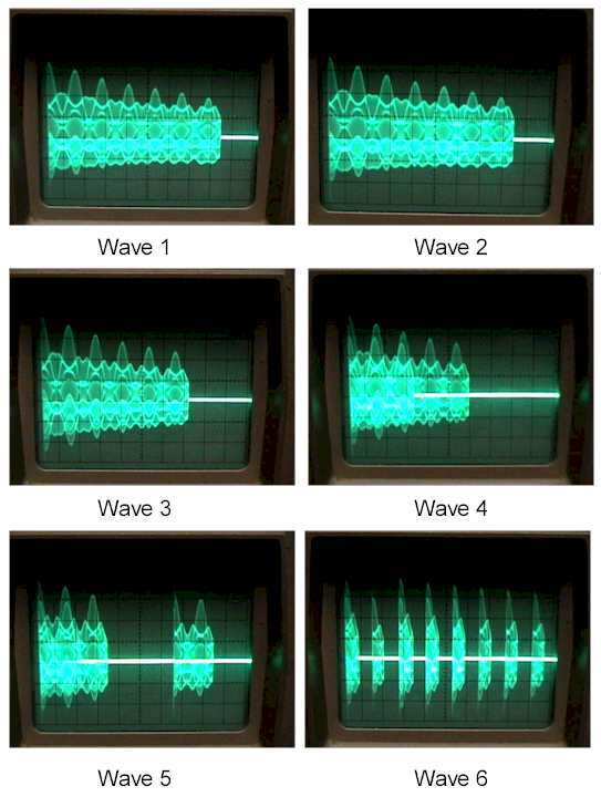
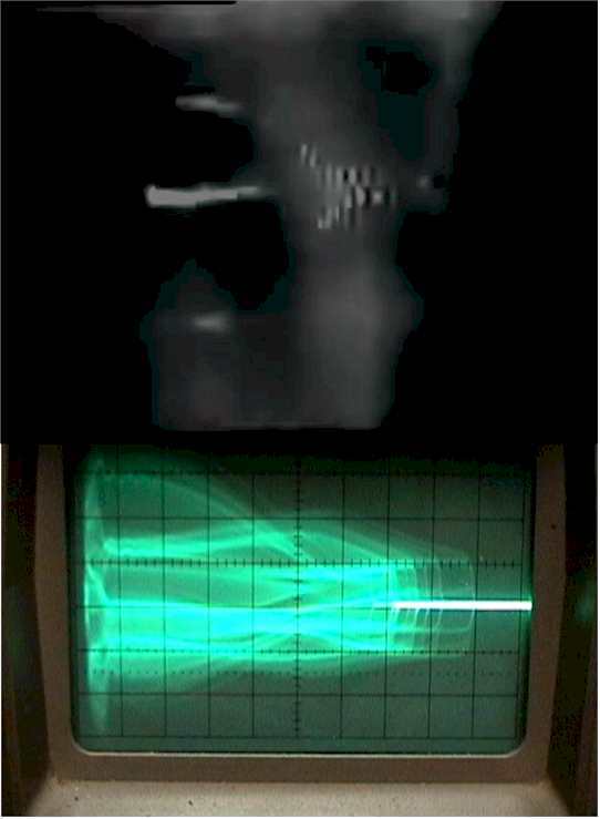
And the envelope of the wave is effectively the first quarter cycle of a 60Hz cosine wave. In some respects this is like a very crude approximation to a damped wave. I believe that the latter is not a design flaw but rather a feature.
(c) Copyright Aubrey Scoon 2002-2009 - Mirror of information from www.scoon.co.uk
The opinions stated on this page are those of Aubrey Scoon (1960-2009). They do not necessarily reflect the opinions of anyone else assocaited with www.rife.de.