Observe Viruses and Bacteria
Microscope
The First Rife Microscope and the Gained Ability to Observe Viruses and the Fine Structure of Bacteria
With an Optical Microscope by the Overcoming of the Fraunhofer Diffraction Limit
by Gary Wade, physicist Date: 12th September 2014
Introduction
This is my second article on the Rife type microscopes, which have the ability to see the fine structure of bacteria and viruses in living medium with visible light, because Dr. Royal Raymond Rife found a way to overcome the Fraunhofer diffraction limit. He did this by using the Principle of Reversibility in optics in a new and novel way. In my first article, Appendix A of another paper I wrote, I went over in some detail the pertinent unique details of Rife type microscopes that make them so special and unsurpassed to this day in magnification and resolution ability with crystal clear clarity of image.(ref.1) In this article I am going to review some of the important points discussed in Appendix A, but I am going to mainly focus on the construction of Dr. Rife’s first microscope build in 1920, which was able to reach 17,000 power magnification (ref. 2). Dr. Rife had INVENTED A NEW METHOD TO MAGNIFY an object by greatly expanding the cross sectional area of a central region of a nearly focused image (converging beam) from a objective lens about its optical axis. This new form of magnification in conjunction with Dr, Rife’s novel method to suppress and essentially eliminate Fraunhofer diffraction phenomenon and the fact that he found a way to also effectively eliminate chromatic aberration, gave the Rife Microscope unsurpassed magnification, size resolution, and crystal clear clarity of vision that no other optical microscope has even come close to.
Intention of Article
My intention here is to write a clear and concise enough article so that the optical engineers, scientists, and students will see how relatively easy it is to build these Rife type microscopes with today’s materials technology, machining technology, and opto-electronics availability. From this realization, then have universities and microscope manufactures start building a new class of world class optical research microscopes. This will or should trigger a research revolution in microbiology and virology. However, it is not only microbiology and virology that need Rife type microscopes for rapid detailed research results. With today’s boom in nanotechnology, micro composite materials technology, and semiconductor devices, there is a great need for a fast accurate way to observe down to the few angstrom resolution level. The properly designed and built Rife type microscope can do this.
Physical Layout of the First Rife Microscope
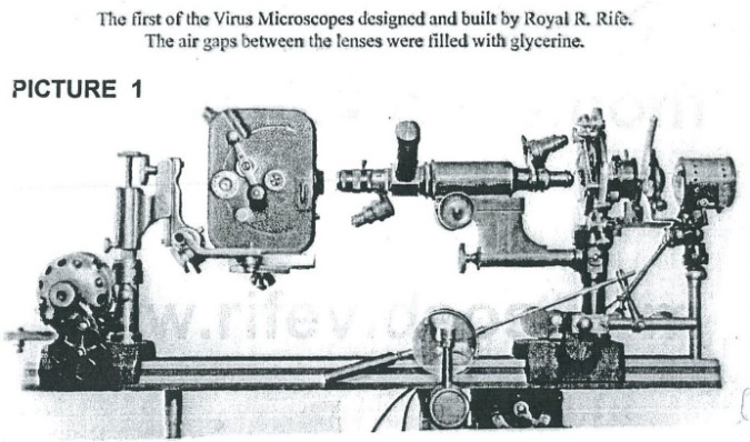
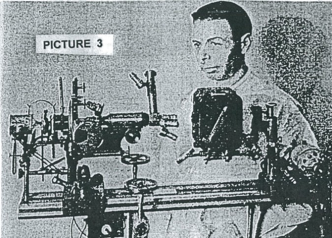
Now that you have been made aware of why you should want to know more about the specifics of the Rife microscope, let us get to it. Pictures 1, 2, and 3 are of Rife’s first microscope. I know of no published plans or specifications for Dr. Rife’s first microscope. So, my writings here about Rife’s first microscope are based upon what I can observe and deduce from what I can see from what appears in Pictures 1, 2, and 3 and other pictures and various news paper articles and journal articles and magazine articles, and from what I know of optics (ref. 3,4,5). Some very useful clues and information of the internal construction of the first microscope can be gained from an article on Dr. Rife’s third microscope, 50,000 power (see Picture 4), which was published in February 1944 issue of The Journal of the Franklin Institute, Vol. 237, titled THE NEW MICROSCOPES, A Discussion by R. E. SEIDEL, M.D, AND M. ELIZABETH WINTER , pages 103 to 130. The same article was also published in the Annual Report of the Board of Regents of The Smithsonian Institution. That is how important they thought it was. This third microscope called, THE UNIVERSAL MICROSCOPE, was designed not only to observe microbes at here to fore unbelievable magnification and size resolution with crystal clear clarity, but was also designed to do microbe dissection (nano- surgery) and collection/abstraction from the environment down to virus size structures. It was also designed to do ultra detailed studies of crystal structures.
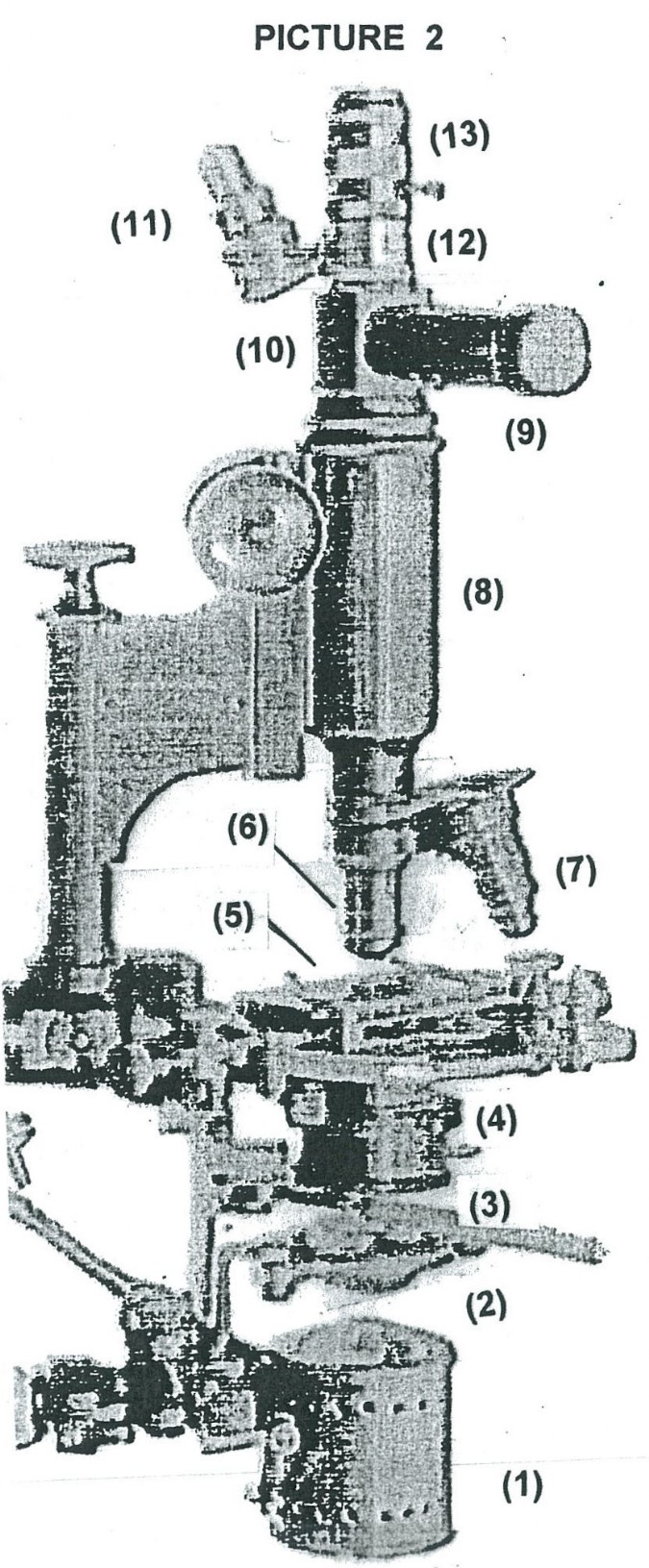
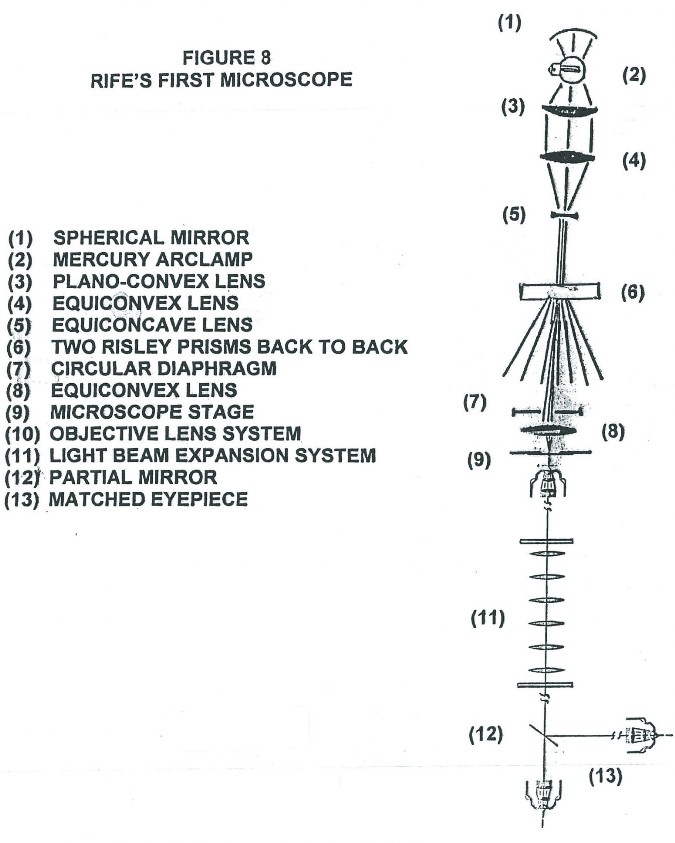
Picture 1 shows the setup using the first Rife microscope used by Dr. Rife to make motion pictures of microbes going about their normal life processes. The rectangular box looking device in front of the microscope eye piece is the motion picture camera. The eye piece of the microscope is the same (matched pair) as the objective lens system of the microscope, except there is an adjustable outer sliding coupler shroud on the lens system needed to couple the camera to it and the eye piece is oriented in the opposite direction to the objective lens system. Picture 2 shows an enlargement of a section of picture 1, where the various components have been given numbers so as to be able to name, describe, and explain what that part (number) does.
- Full spectrum mercury arc lamp system with spherical back mirror and front convex lens.
- Optics take full spectrum white light from mercury arc lamp (1) and make it into a thin rod shaped beam of light for the Risley prisms to work with.
- Two Risley prisms back to back to spread the very narrow white light beam into a broad rainbow spectrum of light that the diaphragm (4) can choke down to a narrow continuous band of frequencies/wavelengths.
- Adjustable diaphragm to help choose only a narrow band of the light frequencies or wavelength window/range wanted for Illumination of the specimen.
- Observation mounting stage for positioning and holding specimens to be observed.
- One of two objective lens systems available in the set up shown and is a matched pair to the eye piece (12) being used with it.
- One of two objective lens systems available in the set up shown and is a matched pair to the eye pieces (11) being used with it.
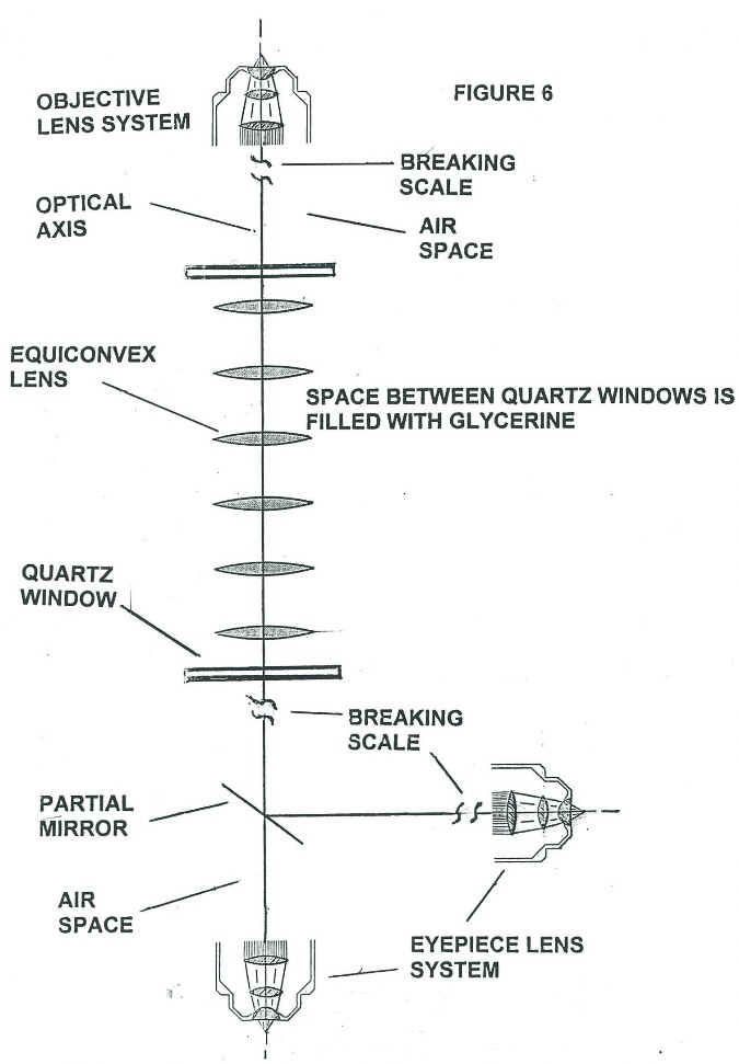
- A cylindrical optical assembly machined out of magnelium, which contains six identical bi-convex lens all equally spaced apart with all their optical axis coincident with each other. The entire lens assembly is immersed in glycerine (see Figure 6) with two quartz windows on the ends to contain the glycerin inside the cylindrical enclosure.
- Hollow tube upon which an eye piece is mounted when microscope is being used for filming, so as to see what is being filmed or just observing without filming.
- A partial mirror beam splitter designed to reflect part of the objective collected light at right angles up the tube (9) to an eye piece (not shown in the picture, see picture 3) to see what the camera is filming.
- A different power eye piece, a matched pair, the same lens system used in the objective lens system (7).
- Microscope eyepiece, part of a matched pair, the same lens system used in the objective lens system (6).
- Sliding adjustable outer shroud on eye piece (12) needed to couple the camera to the eye piece.
Click on images to enlarge.
Classical Optics Review of the Source of the Fraunhofer Diffraction Limit
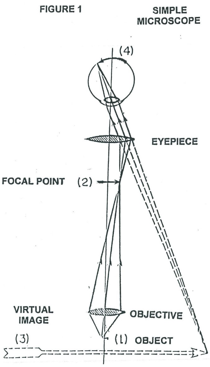
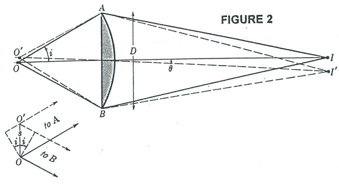
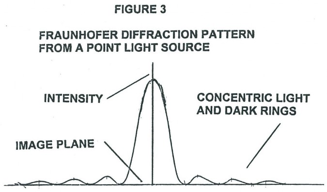
To understand how the magnification and resolving power of the Rife microscope can go beyond that of the commonly used optical microscope, it is necessary to understand the cause of the magnification and resolving power limitations of the ordinary optical microscope. Figure 1 shows the simplest form of a microscope. The object (1) for the objective lens has its image (2) as the object for the eyepiece lens. This object (2) has a final real image formed on the eye retina (4) by the combined lens system of the eyepiece lens and eye lens. And finally, the brain interprets the real image (4) as coming from a virtual object (3). From the point of view of geometrical optics alone, the objective and eyepiece of Figure 1 can each be replaced with lens combinations to give unlimited magnification. However, due to diffraction phenomenon, namely Fraunhofer diffraction, and lens aberration phenomenon there is a practical limit to useful magnification. From theory and experiment it has been found that Fraunhofer diffraction phenomenon is usually by far the dominant limiting factor in determining the resolution ability of a lens system to form an image in currently used microscopes. Figure 2 shows a plano convex lens which has two objects, O and O’. From these the lens form images I and I’ are formed in Figure 2 using only geometrical optics principles. Note that O and O’ are represented by small black dots. Further, note that Figure 2 is a symbolic diagram and therefore the white background could be replaced by black and the black lines and curves could be replaced by any color, yellow for example. The symbolic information contained in the Figure would remain the same. Now let O and O’ be sources of yellow light. I and I’ will now be yellow dots. Let the diameter (size) of the yellow light sources O and O’ become smaller and smaller. The diameter of the images I and I’ will, by geometrical optics principles, also become smaller and smaller. In fact, by geometrical optics principles, as the diameters of O and O’ go to zero so will the diameters of I and I’. However, due to Fraunhofer diffraction phenomenon as the diameters of O and O’ go to zero, the diameters of the images I and I’ converge to a finite non zero size. In fact the images I and I’ of point (zero diameter) light sources O and O’ are concentric light and dark zones as qualitatively illustrated in Figure 3. The light intensity pattern produced in space as illustrated in Figure 3 is that found along any line passing through the center of I (or I’) and at right angles to the shortest line segment joining I (or I’) and O (or O’).
So looking back at Figure 2 we see that if the distance s between the two point (zero diameter) light sources O and O’ becomes small enough, their images I and I’ will begin to overlap. This means that any two self luminous point light sources O and O’ located on an object of interest (the specimen) can not be observed independently unless they are far enough apart so that the center bright zone of theirFraunofer diffraction patterns do not appreciably overlap. In optics the standard derived relationship between s, w, n, and i for the lens of Figure 2 is:
S = (1.22 w) / 2n sin i ; Equation 1.
Where s is the minimum separation between O and O’ where they are just resolved, w is the wavelength of light used, n is the index of refraction of the medium between O (or O’) and the lens surface, and i is the angle as indicated in Figure 2. Substituting appropriate values of w, n, and i into Equation 1, for commonly used high power optical microscopes, gives values for s of around 2,000 Angstroms or .2 microns, which is significantly larger than the mean radius of viruses in general. However, this .2 micron resolution limit is still too optimistic when other distortion effects of lens systems are taken into account. The minimum resolving distance given by Equation 1 does not explicitly contain the diameter (D) of the lens. However, direct examination of Figure 2 clearly shows how i is dependent on D. It is now evident that no matter how much the eyepiece lens magnifies the object (2) of Figure 1, the corresponding size resolution in the final virtual image (3) can be no better than approximately .2 microns.
How Dr. Rife Suppressed the Fraunhofer Diffraction Limitations in Optical Microscopes
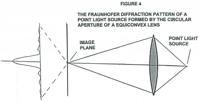
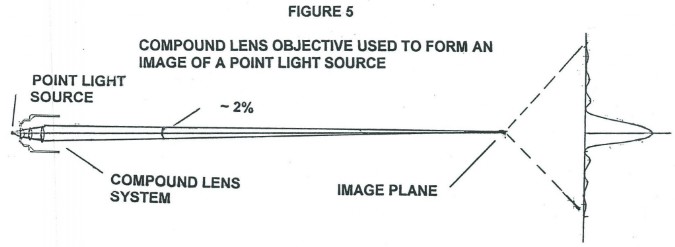
Rife found a way to overcome or suppress the Fraunhofer diffraction limitation, that enabled him to build a microscope that could see viruses and the fine details of bacterial structures that currently used microscopes can not see at all. What Rife did was to apply the Principle of Reversibility in a new and novel way. The Principle of Reversibility states: If a reflected or refracted ray is reversed in direction, it will retrace its original path. This principle has more than a purely geometrical foundation, and can be shown to follow from the application of corresponding mechanics principles to wave motion. In other words diffraction phenomenon (wave phenomenon) is also undone by reversing the path of the light ray (effectively time reversal). In Figure 4 we see a equiconvex lens which has formed the image I, in space, from a point light source object O. As indicated, the image I is not a point but has the form of concentric light and dark zones just as in Figure 3. Now by the Principle of Reversibility, if the diffraction pattern image I of Figure 4, which is formed in space, not on a screen, is sent back through the equiconvex lens (effectively time reversal), the original point image O will be formed, not the normally found diffraction pattern image from a point light source, such as in Figure 3. Note again that, the diffraction pattern image of Figure 4 is formed in space not on a screen. The diffraction pattern image that is being sent back through the lens is effectively a time reversal of light “image”. It is not light back scattered from and image formed on a material screen. Now consider Figure 5 which shows a compound lens objective as used in a high power optical microscope being used to form an image I in space, not on a screen, of a point light source O. As with the single lens objective a point image will not be formed. Instead a Fraunhofer diffraction pattern will be formed as shown. For simplicity theFraunhofer diffraction pattern shown is that of a single lens, however the actual pattern would be a composite of the separate Fraunhoferdiffraction patterns from the three lens in the system. The actual pattern would qualitatively be the same as shown, a strong central light disk, known as the Airy’s disk, surrounded by faint darker and lighter concentric zones. And just as before, if the diffraction pattern image formed in space not on a screen were sent back through the objective lens system a light point image would be formed, not a diffraction pattern image.
WHAT RIFE APPARENTLY REALIZED WAS THAT TO A GOOD FIRST APPROXIMATION HE COULD ESSENTIALLY ELIMINATE FRAUNHOFER DIFFRACTION PHENOMENON AND ACHIEVE HIGH MAGNIFICATION BY USING A EYEPIECE THAT WAS EXACTLY LIKE THE OBJECTIVE USED (MATCHED PAIR), BUT INSTALLING IT IN THE OPPOSITE ORIENTATION (BACKWARDS) TO THAT OF THE OBJECTIVE, WHILE CONCURRENTLY INSERTING AN OPTICALLY SYMMERTIC LIGHT BEAM EXPANDING (MAGNIFYING) OPTICAL ASSEMBLY BETWEEN THE EYEPIECE AND OBJECTIVE (SEE FIGURE 6).
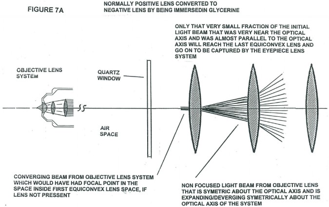
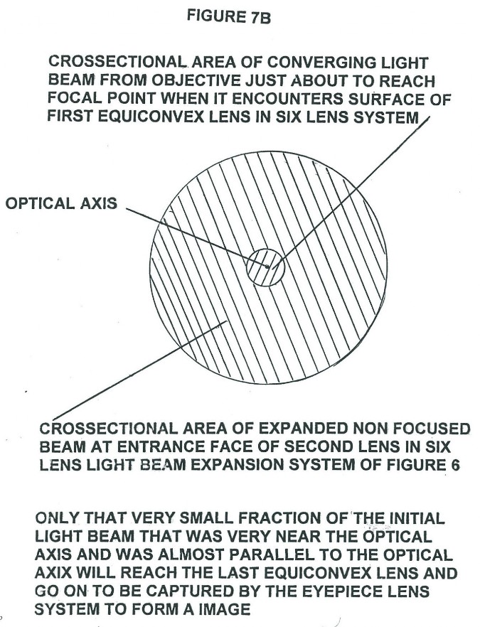
A news paper article, I uncovered in my research that had no date or publication name, indicates there are probably 6 lens in the cylindrical center section of the microscope between the objective and eyepiece, with these lens being immersed in glycerine. The lens configuration probably used six identical double convex normally converging quartz lens, when used in air, equally spaced apart with the space between the lens filled with glycerine as shown in Figure 6. Since the glycerine has a slightly larger index of refraction (1.473) than quartz (1.46), the immersed double convex normally converging positive lens when used in air can be/are converted to diverging / negative lens making light rays traveling parallel or slightly converging, but nearly parallel rays, entering the lens along the optical axis leave the lens slightly diverging as illustrated in Figure 7A. Figure 7A illustrates qualitatively the light ray paths occurring at the beginning of the optical assembly of spherically convex surfaces of the beam expanding optically symmetric assembly shown in Figure 6. Figures 7A and 7B illustrate how the beam of light from the objective IS EXPANDED IN SUCH A WAY THAT ONLY LIGHT RAYS THAT ARE VERY CLOSE AND NEARLY PARALLEL TO THE OPTICAL AXIS OF THE ENTERING CONVERGING BEAM REACH THE EYEPIECE ENTRANCE. Note that just before the converging beam from the objective lens system comes to its focal point to form an image, it encounters the interface between the lens material medium and the glycerine medium at the spherically convex lens surface. THIS CONVERGING BEAM IS CENTERED ON THE OPTICAL AXIS OF THE SHHERICAL SURFACE OF THE FIRST CONVEX LENS IN THE ASSEMBLY. Upon crossing the spherically convex interface the converging beam is starting to be converted into a diverging (expanding) beam about its center axis. As the beam leaves the second surface of the first double convex lens in the assembly, it is now a diverging beam. As this now diverging beam passes through each additional spherically convex surface the central portion of the beam is again expanded about its axial center, the optical axis of the lens assembly. Only a very small fraction of the expanded light beam from each lens reaches the next lens in the assembly in such a way that it will have both further cross sectional expansion or magnification and still reach the last lens in the assembly. It is this greatly expanded (“magnified”) very small portion of the original beam which is focused down into an “image” by the eyepiece. Of course the optical axis of all the convex lens must coincide as closely as possible with each other. It is only a very small fraction of the spherical surface area of the equiconvex lens that is centered about the optical axis of the lens system that processes the light that will actually reach the eyepiece to form an image. That portion of the expanded light beam leaving the convex surface of the last lens and entering the eyepiece lens system needs to have approximately the same divergence (time reversed convergence) angle as the converging light beam leaving the objective lens system. When the expanded portion of the original beam is focused down into an “image” it still contains the Fraunhofer diffraction pattern structure obtained from its passage through the objective lens system. However, the eyepiece, which is identical as possible (matched pair) to the objective lens system, but installed in the opposite orientation, produces a Fraunhofer diffraction pattern structure which to a first approximation undoes essentially all of the originalFraunhofer diffraction pattern introduced by the objective lens system (Principle of Reversibility). What is obtained is a non inverted image with crystal clear clarity and very high resolution mainly limited by the resolving power of the human eye or camera electro-optics used.
Discussion of the Optics of the First Rife Microscope
We will now discuss the optics of this first Rife microscope in more detail (see Figure 8) and then follow up with a modern version which can now be built. The light condenser section of the microscope consists of elements (1) through (4). These concentrate the light from the mercury arc lamp (2) into an intense converging beam of light which is directed onto lens (5). Lens (5) turns the intense converging light beam into a thin pencil shaped parallel beam which is directed to the center of the first Risley prism (6). There are two Risley prisms back to back. The Risley prism, which consists of two counter-rotating circular thin prism wedges, separates the intense pencil of light into a fan shaped spectrum. Once the angle of incidence of the pencil of light to the plane of the Risley prism is held fixed, the angular width and orientation of the spectrum is then determined by the relative angle of rotation between the two prisms (the effective vertex angle of theRisley prism). A small portion of wavelengths of this spectrum falls across the variable diameter circular opening of the diaphragm (7). The settings of the Risley prisms determines the exact wavelength of the light that goes through the center line of the diaphragm and the diameter of the diaphragm aperture determines the spread in wavelength values that goes through the diaphragm with the central chosen wavelength. Lens (8) focuses the chosen wavelength and its associated spread in wave lengths down into an intense spot of light just under the specimen located on the quartz slide on microscope stage (9). The microscope objective (10) acts as a normal microscope objective. However, note that in the original Rife microscopes the various lens making up the objective lens system are not color corrected. They were all constructed of block quartz. This will be discussed further on in the text. The refracted light leaving objective (10) has a very small angle of convergence (approximately one to two degrees). When this refracted light enters the lens system (11) its angle of convergence is converted into an angle of divergence do to the change in index of refraction at the convex lens face. As the beam of light from the objective transits the central lens system of the microscope, it is expanded in diameter about the principal center ray (optical axis). The diverging and expanded light beam exiting from the convex lens face of the last convex lens then enters the matched pair eyepiece (13) with a divergence angle similar to the time reversal angle of convergence of the light beam from the objective and by the Principle of Reversibility essentially all Fraunhofer diffraction phenomenon from the objective lens system is undone and a final image is formed essentially free of all Fraunhofer diffraction phenomenon. Note that the partial mirror (12) used for viewing with the eye and locating what is being photographed, slightly offsets or displaces the path of the central optical axis of the now diverging light beam or cone and the designers and machinists must offset the eyepiece optical axis to coincide with the optical axis of the diverging light cone. Alternatively a counter balanced rotating partial mirror could be used where video camera picture grab time could be synced with partial mirror positioning/location.
Overcoming Chromatic Aberration Phenomenon and No Longer a Need for Microbe Stains
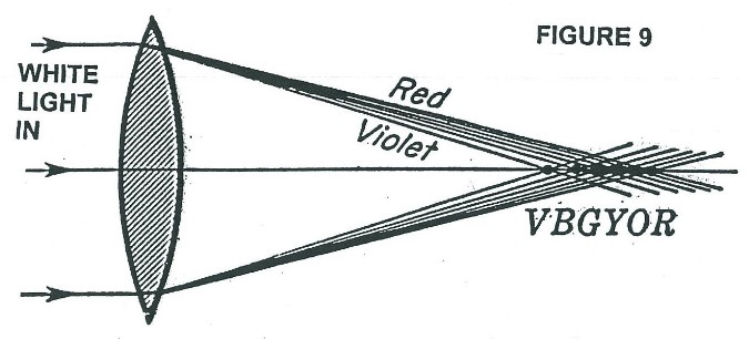
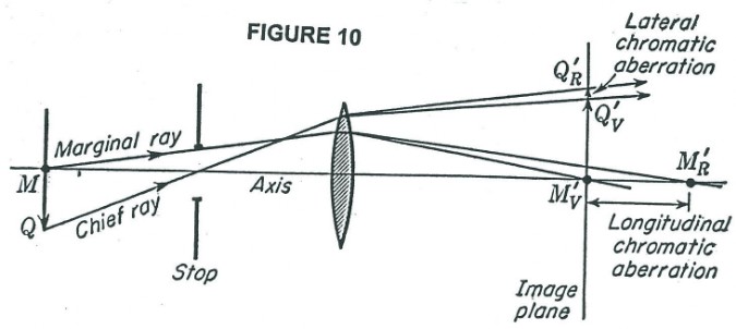
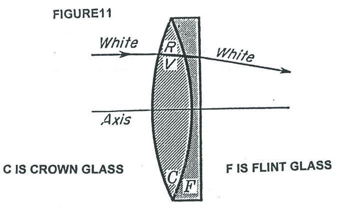
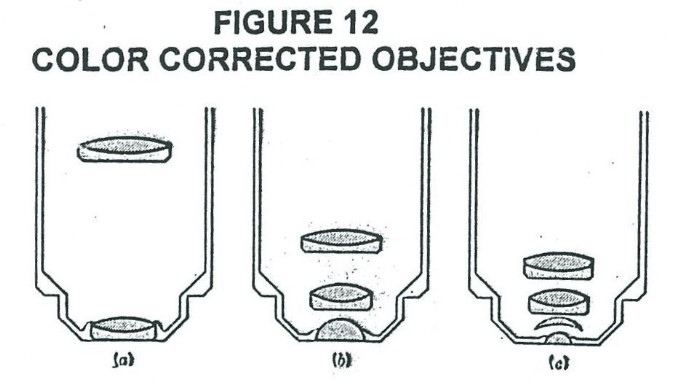
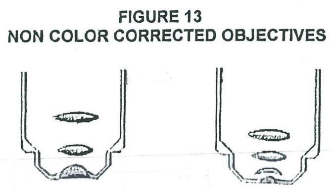
So far we have discussed only diffraction phenomenon as the major limiting factor in the resolving power and therefore the determining factor in the useful magnification of an object. There is another problem of chromatic aberration (see Figure 9), which Dr. Rife had to overcome to achieve the required spatial resolution to see viruses. Figures 9, and 10 illustrate the problem normal lens have in standard high powered optical microscopes when it comes to forming a sharp image of a multicolored object. Figure 9 illustrates how the index of refraction changes with color (wavelength) and therefore the focal point changes with color. The practical consequences of this changing index of refraction with color, is illustrated in Figure 10. The same object, if viewed in different colors, would have different image locations and magnification. Figure 11 shows a cemented doublet made up of a positive equi-convex lens made of crown glass and a negative concave-plano lens made of flint glass. The power of the equi-convex lens is larger in magnitude than the magnitude of the negative power of the concave-plano lens and therefore the combination has a overall positive power. The possibility of color correction by this combination comes from the fact that dispersions produced by different kinds of glass are not proportional in the deviations they produce. Figure 12 shows three different standard type microscope objectives which use the above discussed color correction. However, Rife chose not to use this color correction technique in the objective/eyepiece lens systems of his microscopes. Instead he only used quartz lenses in his objective/eyepiece lens systems (examples show in Figure 13. He was able to get away with non-corrected lenses because when he found the solution to another common problem in microbiology observations with a light microscope, he found he did not need color correction in general. That other common problem is one of making the specimen (bacteria or viruses in Rife’s case) clearly visible. Normally dyes/stains are used to stain bacteria (now dead bacteria after the staining process) to make them clearly visible and identifiable. When it comes to viruses this technique is generally unusable, because of dye pigment size of some stains and other considerations. Rife found that invariably when he looked at any bacterium or virus with his microscope he could always find at least one narrow band of wavelengths of light that made the bacterium or virus luminesce and or fluoresce. Furthermore, the luminescent and or florescent color (narrow band of wavelengths) of the bacterium or virus was unique, just as the wavelength that made it luminesce and or fluoresce. IN OTHER WORDS, RIFE HAD FOUND A WAY FOR THE SPECIMEN TO SELF ILLUMINATE WITH A LIGHT EMISSION OF ONE COLOR, WHICH HE COULD SHARPLY FOCUS ON WITH NON-COLOR CORRECTED LENS. Therefore no color correction was required. There were, however, some exceptions where the microbe would luminescence and or fluoresce with two different colors, but one would generally be much brighter than the other. When focusing the image using the brighter wavelength emission, a dim halo around the object’s image would be seen from the now out of focus dim luminescent and or fluorescence emission wavelength. Two other potential apparent reasons Rife did not use color corrected objective lenses in the microscope are their extra light loss at dissimilar material interfaces (back scatter), and his desire to “see” both visually and photographically farther up toward and into the ultra violet light spectrum range, which a quartz lens system allowed.
A Modernized Version of the First Rife Microscope
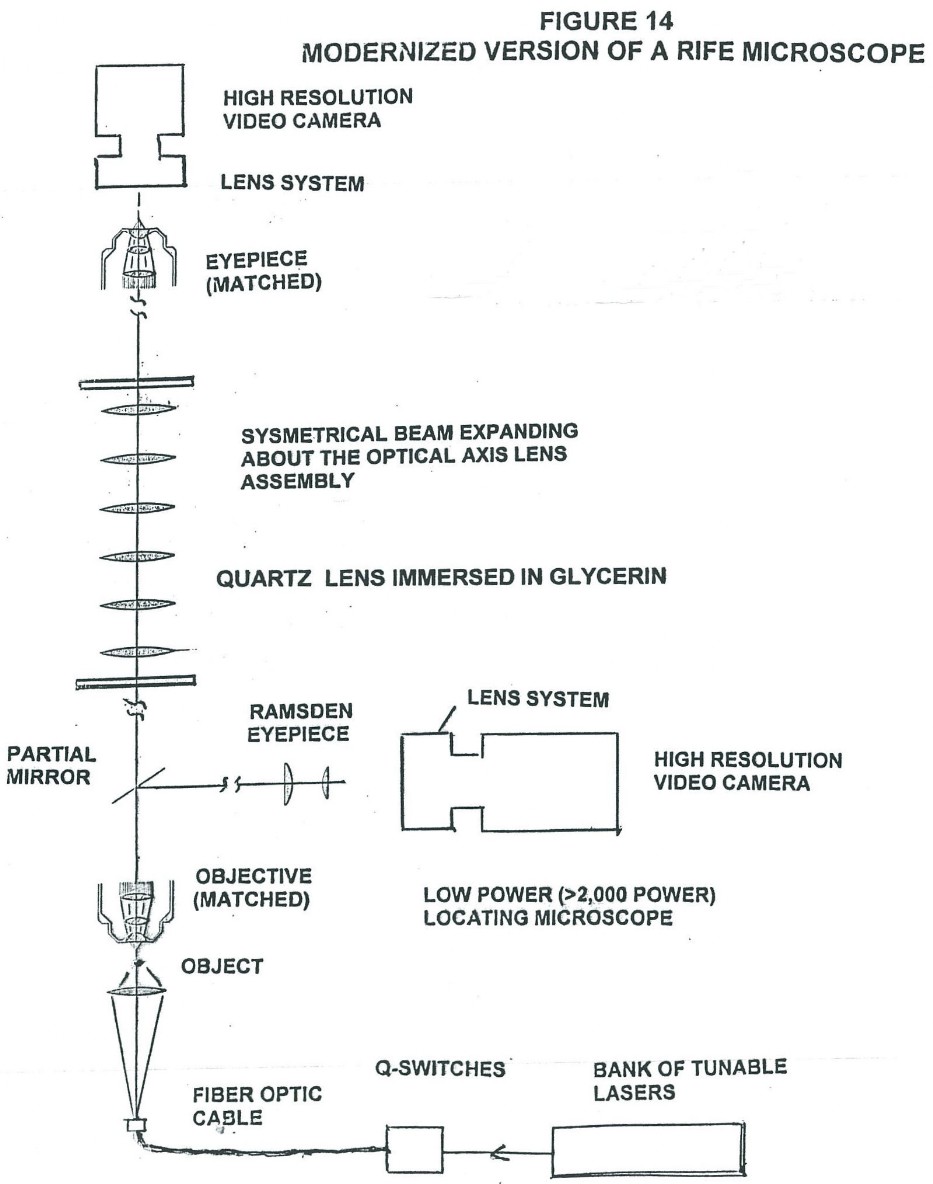
Figure 14 is what a modernized version of a Rife microscope modeled after Rife’s first microscope could look like. This microscope could be built by any present day university using a good optical ray tracing program to design what you want once you understand the principles upon which the Rife type microscope are based. Then you would need the mechanical engineers to figure out how to fixture the lens in the system using material that have essentially the same coefficients of expansion and contraction as the lens material being used (i.e. with quartz you would use the metal alloy magnelium). The cost of this microscope would be much less then the cost of a good research electron microscope.
The advantages of the Rife microscope over the electron microscope are:
- Much shorter sample preparation and set up time for both biological and inanimate objects.
- The sample (bacterium or virus) is seen in its natural environment, not distorted/destroyed by the sample preparation procedure and observation processes (high energy electron bombardment). A similar statement would hold true for nano technology material.
- With the large number of protein and compound specific fluorescent molecular tags available currently, the Rife type microscope used in conjunction with ultra high speed and synchronized Q-switched (shuttered) tunable laser sources could make slow-motion high resolution (under 50 angstroms) motion pictures or videos of a multitude of cellular processes. (The use of high quality color corrected lens is potentially being assumed here)
- It is far cheaper to run and maintain and takes up much less space.
- Many medical conditions and diseases whose cause are currently unknown, would be quickly and definitively shown to be pathogenic in nature. Just as Rife discovered in the 1920’s and 1930’s. The electron microscope is far to time consumptive per sample and has serious data interpretation problems.
What the actual limits of resolution and therefore effective useful magnification will be for the modern Rife type microscopes is not known. However, there is every reason to believe that it can easily surpass that of the best currently available electron microscopes.
Conclusion
The here to fore thought Fraunhofer diffraction limit, which limits currently designed and used optical microscopes to a resolution size in the range of .2 microns and useful magnification to around 3,000 power can and was greatly overcame by the First Rife Microscope constructed in 1920 and by the four other Rife Microscopes built by Dr. Rife (ref. 6).
There is a great need today for Rife type microscopes in microbiology, virology, material science technology, nanotechnology, and micro electronics. These needs could and should be met by the construction of modern production versions of Rife type microscopes.
As of the writing of this article, Dr. Rife is (2014 – 1920 = 94) years ahead of his time and counting. I am sure Dr. Rife would want us to catch up. He attempted to get us caught up by putting his third microscope (50,000 power) on long term loan to the California Institute of Technology back in the mid 1950’s, but Cal Tech dropped the ball. Several generations have passed now, so perhaps the current generation can pick up the ball and carry it across the goal line to bring us all the fruits of a revolution/renaissance in microbiology, virology, nanotechnology, materials technology, and micro electronics.
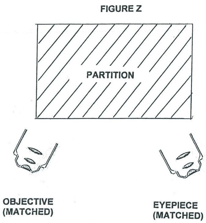
HOME WORK PROBLEM FOR THE BRIGHT ONES
In Figure Z below is shown a Rife type microscope system where a matched pair of objective and eyepiece lens systems are being used in conjunction with a single machined block of quartz or clear sapphire (hidden from view by partition). Determine a machined shape of all surfaces, relative orientation, and dimensions of the machined block to obtain 500,000 power magnification, with 5 angstrom resolution. Be sure to precisely define the surface of both the entrance and exit ports for the light going from the objective into the block and going to the eyepiece. Assume focal length of objective lens is .2 meters with a convergence angle of 2 degrees and the objective lens is 250 power. HINT: Use whatever wavelength of light you want that is compatible with optical materials used throughout the optical system. You will use total internal reflection inside the machined block to cut down on (stop) light intensity loss and you are allowed to use one normal mirror surface (i.e. silver deposited on machined/polished plane surface).
References: