
1939 Beam Ray Machine
1938, A group of British researchers headed by Dr Bertram Winter Gonin, sought to buy some experimental machines from Rife to confirm his work. At that time, Rife had no commercial operation capable of handling the orders, and at the instigation of his old friend Ben Cullen, Rife consented to the formation of a commercial company called Beam Rays Inc. At that time, the majority owner of the rights to the machine was an electronics engineer called Philip Hoyland. Hoyland had designed and developed all of the original Rife machines since late 1934. Hoyland and Rife became partners in Beam Rays Inc. The company produced a small number of machines but suffered internal conflicts because of the actions of some of the other partners and because of frictions between Hoyland and Gonin's group. Hoyland believed that Gonin and his partners were trying to steal the technology for themselves. Subsequently, the company was destroyed in 1939/1940 when Hoyland brought a lawsuit against Beam Rays in an attempt to stop one of the partners from illegal stock trading and also to dissolve the contract with the British. Fuller details of this are being written up and will be posted here in the near future.
The Beam Ray Corporation produced a number of machines. I'm not sure of the exact number as I have seen varying accounts, but I believe that about 17 machines were produced and shipped to MD's in California. Another four machines were shipped to England to Dr B. Winter Gonin of the London School of Tropical Medicine. There was some argument between Rife and Hoyland over these machines and their operating principle, however various MD's including James Couche used one of these machines for many allegedly successful treatments of patients for many years.
The U.K. Rife Research Group managed to get access to one of the machines believed to be one of the originals that were shipped to California in the late 1930's. I reverse engineered that machine and present the results below. I have a lot of data on this machine of which this is only part, I will add things as I get time as much of the data needs to be organised properly. The exact date of the machine is unknown - we know that it was built sometime between the autumn of 1938 and the early part of 1939 - so it may actually be a 1938 machine.
I would like to express my thanks to Robert Harrison, an expert valve/tube engineer (I'm not a valve/tube expert) who gave me massive help and support during the reverse engineering process and who corrected numerous silly mistakes that I made! My thanks also to Stuart Andrews and Bob Haining for their help and support in this effort.
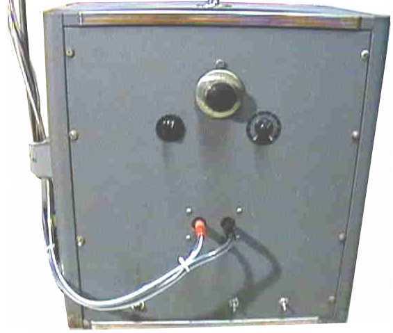
Below are the machine schematics and links to some photographs. The schematics have been rendered into PDF format which allows them to be zoomed to resolve fine detail.
WARNING: These schematics are presented for information only. Do not try to construct a copy of this machine unless you are knowledgeable and experienced in high voltage valve/tube work. The tube filaments need to be heated for a couple of minutes before switching on the HT - failure to do this will blow them. In addition, some parts of this circuit use up to 1750 volts DC at substantial current and can easily kill in inexperienced hands.
Output Stage Schematic
Complete Schematic
Original Plasma Tube Schematic
Beam Ray Machine Waveform Photographs
Here are various photographs I took of the machine's waveforms on an oscilloscope. Note: these were taken with the 812A tube in place. The waveforms produced when an 809 is used are smoother and more sinusoidal.
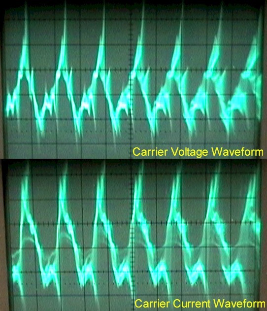
Carrier Waveforms
These are the carrier waveforms for both voltage and current. The actual carrier frequency of the machine depends very much on the plasma tube and also on coupling effects between the tube and any person in the vicinity.
This has made it very difficult to get accurate measurements of the machine because even being in the same room as the machine causes the frequency to alter!
However, after many experiments I am reasonably certain that the resting carrier wave frequency, undisturbed by any local effects is approximately 3.33 MHz.
Because the wave is not a pure sine there are strong harmonics at many other frequencies as well. Some of the dominant harmonics have been observed at approximately 2.3 MHz, 4.6 MHz and 9.09 MHz.
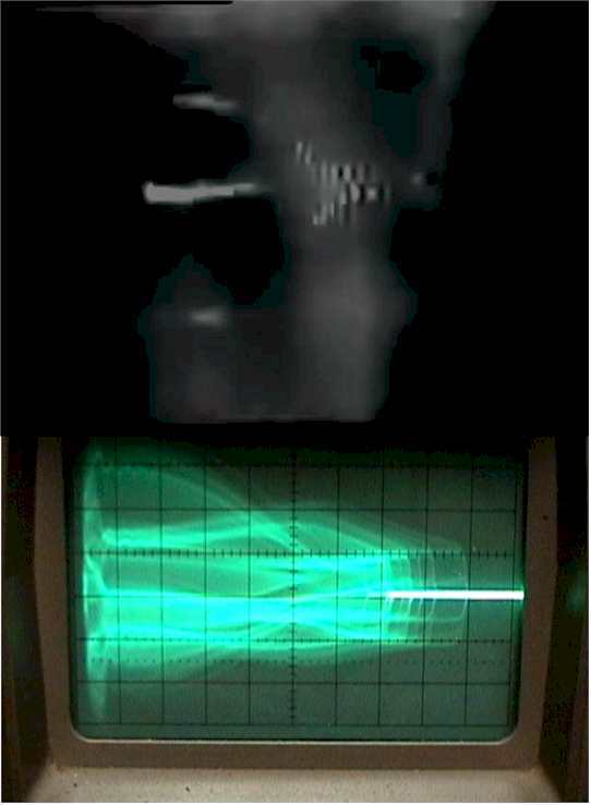
Comparison to Rife Machine
Comparison of wave from original Rife machine (top) with the waveform from the Beam Rays machine.
Note the similarities in the wave envelopes.
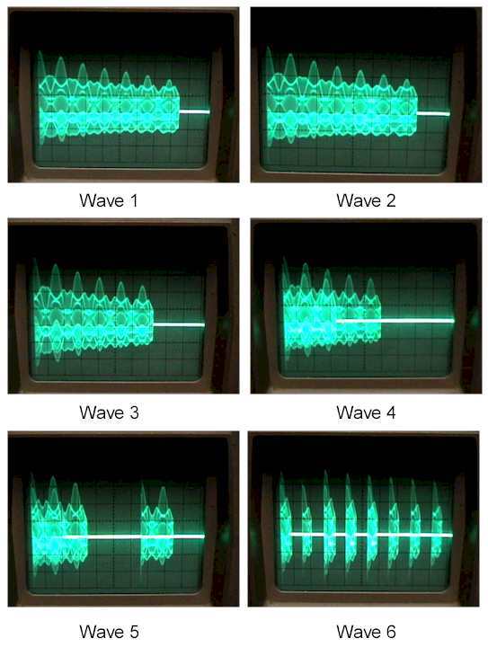
Effect of Modulation Depth
Wave 1 - this is one burst of the tank waveform at 1430 Hz (scope settings on uncalibrated and adjusted for better resolution) and in excess of 90% modulation depth (sine wave).
Wave 2 through Wave 4, this is what happens as the modulation depth is successively increased - Wave 4 is pretty much 100%. The number of cycles per burst (a burst is approx 20ms apart and is set by the mains cycle) decreases with increasing modulation.
Wave 5 - as you enter overmodulation, the burst breaks up into smaller chunks.
Wave 6 - at approx 50V p-p modulation the wave is overmodulated and consists of single cycle pulses grouped into bursts.
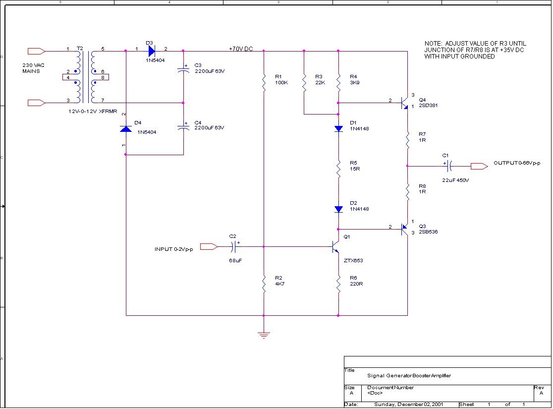
Booster Amplifier Schematic
Below is a third schematic. This is for a transistor booster amplifier I designed. It is possible to separate the Beam Ray machine output stage from the oscillator stage and to drive the output stage directly from a modern digital frequency generator. This allows much more precise and accurate frequency control than the original. But the output stage requires over 40 V p-p to drive it properly at 100% modulation and most modern generators are not capable of outputting this kind of voltage. So the booster stage allows a low level signal between 20Hz and 200Khz (the original range of the machine) to drive the output at up to approx 66 V p-p without significant signal distortion (it can be driven at higher inputs of up to 2 V p-p with clipping). An input of 951 mV will cause 100% modulation of the Beam Rays machine and an input of 1.5 V p-p will result in significant overmodulation without distortion of the modulating signal itself. The booster amplifier has a bandwidth of approximately 800KHz and so can also be used as a general purpose wideband, high voltage buffer amplifier as well.
(c) Copyright Aubrey Scoon 2002-2009 - Mirror of information from www.scoon.co.uk
The opinions stated on this page are those of Aubrey Scoon (1960-2009). They do not necessarily reflect the opinions of anyone else assocaited with www.rife.de.